PREMIUM HARD TO FIND PC ITEMS:
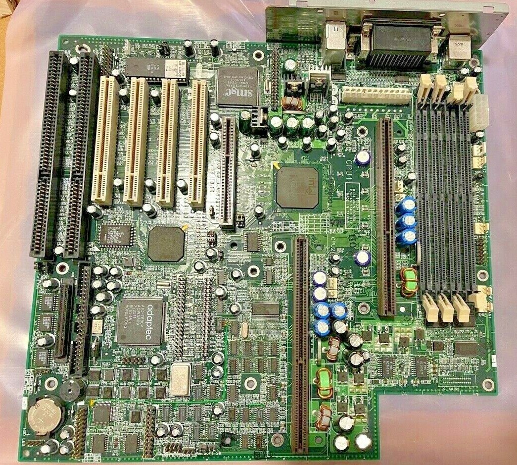
RARE ACER ALTOS M17A DUAL SLOT 1 FULL SIZE ATX MOTHERBOARD WITH ON BOARD ADAPTEC SCSI ACER P/N: 48.53A01.011. MANUAL, CABLES AND CD DRIVER NOT INCLUDED. CPU NOT INCLUDED.
** USA Seller **THE ONLY LISTING ON !
FLAT USPS PRIORITY Shipping
ACER, INC.
ACERALTOS 930 (M17A), M17A
Device Type
Mainboard
Processor
Pentium II
Processor Speed
233/266/300MHz
Chip Set
Intel 440LX
Maximum Onboard Memory
512MB (SDRAM supported)
Cache
256/512KB (located on Pentium II CPU)
BIOS
Acer
Dimensions
305mm x 244mm
I/O Options
32-bit PCI slots (4), floppy drive interface, IDE interfaces (2), SCSI interface, Wide Ultra SCSI interface, parallel port, PS/2 mouse port, serial ports (2), feature connector, USB connectors (2), ATX power connector, AGP slot
CONNECTIONS
Purpose
Location
Purpose
Location
AGP slot
AGP
Floppy drive interface
CN18
ATX power connector
ATX
Soft off power supply
CN19
Power connector
CN1
Chassis fan power 1
CN20
Chassis fan power 3
CN3
IDE interface 1
CN21
Chassis fan power 2
CN4
Power LED
CN22
3.3v power
CN6
IDE interface 2
CN23
USB connector 1
CN7
Reset switch
CN24
USB connector 2
CN7A
RDM connector
CN25
CPU 1 fan power
CN9
Redundant power status connector
CN26
Thermal sensor connector 1
CN10
RDM connector
CN28
Parallel port
CN11
Feature connector
CN29
Serial port 1
CN11A
SCSI interface
CN30
Serial port 2
CN11B
Housing door connector
CN31
IDE interface LED
CN14
Ultra Wide SCSI interface
CN32
PS/2 mouse port
CN15
Speaker
CN33
CPU 2 fan power
CN16
32-bit PCI slots
PC1 - PC4
Thermal sensor connector 2
CN17
USER CONFIGURABLE SETTINGS
Function
Label
Position
»
Factory configured - do not alter
CN2
Unidentified
»
Factory configured - do not alter
CN5
Unidentified
»
Factory configured - do not alter
CN27
Unidentified
»
Power down for 250W power supply enabled
JP1
Pins 2 & 3 closed
Power down for 250W power supply disabled
JP1
Pins 1 & 2 closed
»
BIOS type select Acer
JP8
Pins 1 & 2 closed
BIOS type select OEM
JP8
Pins 2 & 3 closed
»
Password disabled
JP9
Pins 2 & 3 closed
Password enabled
JP9
Pins 1 & 2 closed
»
Buzzer enabled
JP11
Pins 1 & 2 closed
External speaker enabled
JP11
Pins 2 & 3 closed
»
Termination enabled
JP12
Pins 1 & 2 closed
Termination switchable through SCSI select utility
JP12
Pins 2 & 3 closed
DIMM CONFIGURATION
Size
Bank 0
Bank 1
Bank 2
Bank 3
8MB
(1) 1M x 64
None
None
None
16MB
(1) 2M x 64
None
None
None
16MB
(1) 1M x 64
(1) 1M x 64
None
None
24MB
(1) 2M x 64
(1) 1M x 64
None
None
DIMM CONFIGURATION (CON'T)
Size
Bank 0
Bank 1
Bank 2
Bank 3
24MB
(1) 1M x 64
(1) 1M x 64
(1) 1M x 64
None
32MB
(1) 4M x 64
None
None
None
32MB
(1) 2M x 64
(1) 2M x 64
None
None
32MB
(1) 1M x 64
(1) 1M x 64
(1) 1M x 64
(1) 1M x 64
40MB
(1) 4M x 64
(1) 1M x 64
None
None
48MB
(1) 4M x 64
(1) 2M x 64
None
None
48MB
(1) 2M x 64
(1) 2M x 64
(1) 2M x 64
None
64MB
(1) 2M x 64
(1) 2M x 64
(1) 2M x 64
(1) 2M x 64
64MB
(1) 8M x 64
None
None
None
64MB
(1) 4M x 64
(1) 4M x 64
None
None
72MB
(1) 8M x 64
(1) 1M x 64
None
None
80MB
(1) 8M x 64
(1) 2M x 64
None
None
96MB
(1) 8M x 64
(1) 4M x 64
None
None
96MB
(1) 4M x 64
(1) 4M x 64
(1) 4M x 64
None
128MB
(1) 16M x 64
None
None
None
128MB
(1) 8M x 64
(1) 8M x 64
None
None
128MB
(1) 4M x 64
(1) 4M x 64
(1) 4M x 64
(1) 4M x 64
136MB
(1) 16M x 64
(1) 1M x 64
None
None
144MB
(1) 16M x 64
(1) 2M x 64
None
None
176MB
(1) 16M x 64
(1) 2M x 64
(1) 2M x 64
(1) 2M x 64
192MB
(1) 16M x 64
(1) 8M x 64
None
None
192MB
(1) 8M x 64
(1) 8M x 64
(1) 8M x 64
None
256MB
(1) 16M x 64
(1) 16M x 64
None
None
256MB
(1) 8M x 64
(1) 8M x 64
(1) 8M x 64
(1) 8M x 64
272MB
(1) 16M x 64
(1) 16M x 64
(1) 1M x 64
(1) 1M x 64
288MB
(1) 16M x 64
(1) 16M x 64
(1) 2M x 64
(1) 2M x 64
320MB
(1) 16M x 64
(1) 16M x 64
(1) 4M x 64
(1) 4M x 64
384MB
(1) 16M x 64
(1) 16M x 64
(1) 16M x 64
None
512MB
(1) 16M x 64
(1) 16M x 64
(1) 16M x 64
(1) 16M x 64
Note: Board accepts SDRAM memory.
Note: 256KB/512KB cache is located on the Pentium II CPU.
CPU SPEED SELECTION
CPU speed
Clock speed
Multiplier
JP5/pins 1 & 2
JP5/pins 3 & 4
JP5/pins 5 & 6
JP5/pins 7 & 8
JP6
266MHz
66MHz
4x
Closed
Closed
Closed
Open
1 & 2, 4 & 5
300MHz
66MHz
4.5x
Closed
Open
Closed
Open
1 & 2, 4 & 5
333MHz
66MHz
5x
Closed
Closed
Open
Open
1 & 2, 4 & 5
Note: Pins designated should be in the closed position.
CPU TYPE SELECTION
Type
JP3
JP4
»
CPU1 installed
Pins 1 & 2 closed
Pins 1 & 2 closed
CPU2 installed
Pins 2 & 3 closed
Pins 2 & 3 closed
Both slots installed
Pins 2 & 3 closed
Pins 1 & 2 closed